新闻中心/ News
2022年12月简报--- November 2022 Newsletter


November 2022 Newsletter
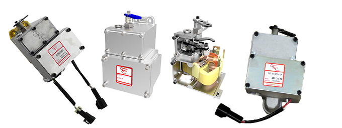
Integrated Pump Mounted Actuators
The 175 Series Integrated Pump Mounted Actuators are field-proven proportional actuators designed to mount directly to Bosch P style fuel injection pumps to achieve an integrated proportional servo fuel package. The design has no sliding parts, and its components are sealed, resulting in outstanding reliability with no maintenance required. The design is versatile with numerous options and mounting kits available to adapt to other fuel pumps.

Application of the Month

12/24 V DC
Fast response; less than 35 ms (10–90%)
Mounts directly to fuel injection Bosch P style pump in place of a mechanical governor
Optional orderable features include feedback sensors and shutoff levers
Supports right-hand racks
Adjustable fuel limits
Manual shut-off mechanism
A large variety of installation kits are available
Application of the Month
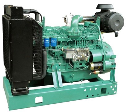
175 on a FAW Engine
This FAW Jeifang (Wuxi Diesel) CA6DF2-17D / 125 kW / 1500 rpm / 24 V DC with Shanghai Denso in-line pump with RSV Type Governor is used in a Synchronized Power Generation application.
The conversion to a GAC ADD175A-24 actuator with installation kit KT175-RS-R and ESD5500E controller was quick and easy.

Actuator: ADD175A-24
Governor: ESD5500E
Installation Kit: KT175-RS-R
Connector and Harness Assembly: CH1215
Magnetic Speed Pickup
Tech Tip
MSP Installation
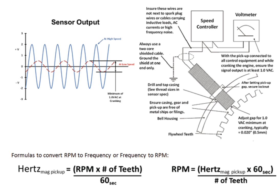
Selecting and installing an MSP may seem complicated, but with some basic information, you can do it right.

1.If no mounting location is available, drill and tap a hole in the flywheel housing. The threaded hole should be centered over the flywheel ring teeth, and perpendicular to the center line of the crankshaft. 
2.Insert the magnetic speed pickup into the hole and turn it until the magnetic speed pickup makes contact with the face of the gear.
3.Back out the magnetic pickup by turning it counterclockwise about 3/4 of the way. The gap between the pickup and the gear should be between 0.020–0.035 in [0.50–0.89 mm]. Digital speed controllers may require less gap (1/4 turn) to provide an optimal signal similar to the Sensor Output shown here.
4.Twist the wire leads for their entire length from the magnetic speed sensor to the control unit. Shielding is required if external interference is present, or the leads are longer than 10 ft [3 m].
Closing Notice
Thanksgiving
Our office will be closed on Thursday, November 24th and Friday, November 25th for Thanksgiving. We will return your calls on Monday, November 28th.
Subscribe to the Newsletter


